- APPLY FOR SLOT
- Internal Users
- External Users
- SLOT BOOKING STATUS
Vibrating Sample Magnetometer Laboratory
Phone : +91-3222-283824
Location : OB / GF / 3, CRF
Facilitator :
Prof. Amal Kumar Das, Physics
Email: amal@phy.iitkgp.ac.in, Contact:+91-3222-283824
For Internal Users - Click Here to apply for Slot
For External Users - Click Here to apply for Slot
Objectives
Measurement of magnetization, susceptibility, permeability as a function of temperature and magnetic field of bulk, film and powder samples.
People

Prof. Amal Kumar Das
Facilitator
Physics
amal@phy.iitkgp.ac.in
+91-3222-283824
Equipment Details
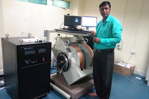
Vibrating Sample Magnetometer
Name- Vibrating Sample magnetometer (VSM)
Manufacturer- Lake Shore cryotronics, USA
Model- 7400 Series
Year of Installation- 2016
Specification: -
| Sample cross- section | 4.5mm × 4.5 mm ( 0.178in × 0.178 in ) |
| Sample height , maximum | ~ 3.2mm (~ 0.125in ) |
| Pin –to- pin spacing | 0.9 mm (0.036in ) |
| Total pin spacing | 2.7 mm (0.108in ) |
| Current | 1 μA – 100μA |
| Compliance Voltage | 5V |
| Contact formation | User adjustable time, current , and voltage |
| Nominal resistance range | 50mΩ – 10 MΩ |
| VSM compatibility | 7400 series |
Utility and Working Principal
A vibrating sample magnetometer (VSM) system is used to measure the magnetic properties of materials. The vibrating component causes a change in the magnetic field of the sample, which generates an electrical field in a coil based on Faraday’s Law of Induction. If the sample is placed within a uniform magnetic field H, a magnetization M will be induced in the sample. In a VSM, the sample is placed within suitably placed sensing coils, also held at the desired angle and the vibrating sample component is made to undergo sinusoidal motion, i.e., mechanically vibrated. The electromagnet activates before the testing starts so if the sample is magnetic, it will become more so the stronger the field that is produced. A magnetic field H appears around the sample and, once the vibration begins, and then the magnetization of the sample can be analysed as changes occur in relation to the timing of movement. Because magnetic flux changes induce a voltage in the sensing coils that is proportional to the magnetization of the sample. Changes in the signal are converted to values by the software to graph magnetization M versus the magnetic field H strength, often referred to as a hysteresis loop.
Sample Details
Choosing sample holder depends on your sample’s shape and size.
|
Thin film |
Length < 1 cm , breadth < 0.5cm |
|
Powder |
15- 20 gm |
|
Solid sphere diameter |
2.8 mm |
MH test of Ni (Standard Sample) sphere
