- APPLY FOR SLOT
- Internal Users
- External Users
- SLOT BOOKING STATUS
Raman Spectrometer Laboratory
Phone : +91-3222-283856
Location : OB / GF / 2, CRF
Facilitator :
Prof. Anushree Roy, Physics
Email: anushree@phy.iitkgp.ac.in, Contact:+91-3222-283856
For Internal Users - Click Here to apply for Slot
For External Users - Click Here to apply for Slot
Objectives
(some examples in some fields)
In geological material analysis:
chemical identification
characterization of molecular structure
effect of bonding, environment and stress
In chemistry Phase identification
Characterization of molecular structure
In biology/medicine
As non-invasive diagnostic tool
Biochemical information
Protein conformation
In material science
Material characterization
In physics
Electron phonon interaction
Electronic resonance effect in phonons
Dynamics of fractal network
Behaviour of Acoustic phonon
Surface science
In art
For restoration/conservation
Other fields, where the technique is used extensively
Biosecurity
Display Technologies
Environmental
Food & Beverages
Forensic
Industrial Process
Nanotechnology
Cosmetics
Photovoltaic / Solar Cell
People

Prof. Anushree Roy
Facilitator
Physics
anushree@phy.iitkgp.ac.in
+91-3222-283856
Equipment Details
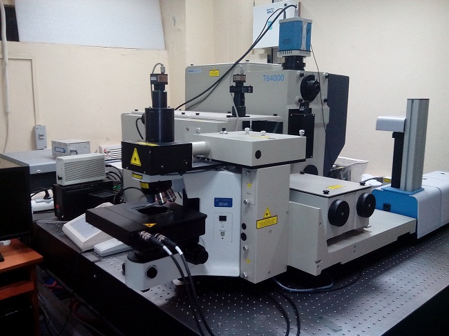
RAMAN SPECTROMETER
Excitation source: Argon-Krypton mixed ion gas laser. MODEL 2018 RM (Make Spectra Physics, USA)Spectrometer : MODEL T64000 (Make Jobin Yvon Horiba, France)
Detector : Thermoelectric cooled front illuminated 1024 256 CCD. MODEL SynpseTM (Make Jobin Yvon Horiba, France)
Collection Optics: Optical Microscope MODEL BX41 (Make Olympus, Japan)
TECHNICAL SPECIFICATIONS
Basic Configuration Optical Diagram for the Spectrometer
- Axial entrance slit
Round plates: Fixed mirrors
Presently Available Configuration: Single Monochromator Configuration (Double Subtractive Mode)
 The double subtractive foremonochromator is used as an tunable filter in the spectral range defined by the scanning mechanism and the gratings. A polychromatic radiation enters the first monochromator through the entrance slit S1 and is dispersed by the grating G1. The exit slit of the first monochromator (entrance slit of the 2nd monochromator) Si1/2 selects a bandpass between l1 and l2. The grating G2 in the 2nd monochromator recombines all the dispersed radiations on the exit slit Si2/3 giving again a polychromatic radiation, but limited to only the spectral range between l1 and l2. The polychromatic radiation selected by the foremonochromator between l1 and l2 is dispersed by the grating G3 of the spectrograph. The spectrum is acquired with a multichannel detector which is mounted in the plane of the exit image or with a monochannel detector through an exit slit. See following diagram.
Focal length of the spectrometer for present configuration: 640mm
Low frequency: < 100 cm-1
Step size: 0.00066 nm (0.03 cm-1)
Grating: 1800 grooves/mm
Grating efficiency curve

Table for dispersion and resolution
|
Wavelength of excitation source (nm) |
Corresponding wavenumber (cm-1) |
Dispersion (cm-1/mm) |
Total dispersion on CCD chip* (cm-1) |
Dispersion /pixel** (cm-1) |
Resolution (Min. 3 pixels to define a peak) (cm-1) |
|
400 |
25000 |
46.55 |
1210.3 |
1.18 |
3.54 |
|
500 |
20000 |
27.83 |
723.58 |
0.71 |
2.13 |
|
600 |
16667 |
17.86 |
464.36 |
0.45 |
1.35 |
|
700 |
14286 |
11.53 |
299.78 |
0.29 |
0.87 |
*dimension of the chip 26 mm´26 mm ** CCD format 1024´256
Basic specification for the CCD
CCD format: 1024´256 Front illuminated open electrode CCD
Pixel size: 26 mm´26 mm
Quantum efficiency

Basic specification for the laser
Wavelength and Maximum Power
|
Wavelength of excitation source (nm) |
Laser Power at laser head (mW) |
Power on the sample using 10´ objective (mW) |
|
487.986 |
200 |
15 |
|
514.532 |
220 |
15 |
|
647.088 |
220 |
22 |
(note: it is only power not power density on the sample)
Collection optics
Visible confocal microscope with X-Y manual mechanical stage
and a revolver equipped with 3 achromatic objectives
10´ visible, NA= 0.25, WD=10.6 mm
50´ visible, NA= 0.75, WD=0.37 mm
100´ visible, NA= 0.90, WD=0.21 mm
Measurements will be carried out at room temperature
PURCHASE SOURCE:
Institute Funding, Year Of Installation September 2011
Utility and Working Principal
Sample Details
SAMPLES PREPARATION FOR MEASUREMENTS
Sample Preparation Required: Nil
Please bring micropipette or special spatula, if they are required to handle the sample.
VOLATILE SAMPLES ARE STRICTLY PROHIBITED.
POWDERED SAMPLE WILL BE ENTERTAINED ONLY WITH 10´ MICROSCOPE OBJECTIVE.